Writing a shader
In Cascade, effects are implemented as GLSL shaders and processed on the GPU.
This has several advantages:
The parallel nature of GPU processing is a perfect fit for image processing. Aka it’s fast.
GLSL is a simple language that is easy to learn.
Processing algorithms are contained in small, portable shader files.
There exists a large amount of reference code for all kinds of image processing applications.
Here we are going to see how we can write our own shader, and run it on the GPU.
What is GLSL
The OpenGL Shading Language is the principal shading language for OpenGL with a straight-forward syntax inpired by C.
Every GLSL shader is a self-contained program, to be run on the GPU.
Getting started
Fire up Cascade and load an image in the Read Node. You do this by double-clicking the node and then clicking on the Load button.
To view the image, with the Read node still selected, press F4.
Now, we need to create a GLSL Shader node. Right click on the node graph (bottom window) and in the menu choose Filter > GLSL Shader.
Connect the output from the Read node to the RGB back input of the GLSL Shader node. Click the GLSL Shader node and press F4 to view it.
The image should be the same as before, since the default shader does not do anything except for passing the image through.
On the right side you will now see the code editor, containing the default shader. You can click and drag to expand the window, so you can see the code a little better.
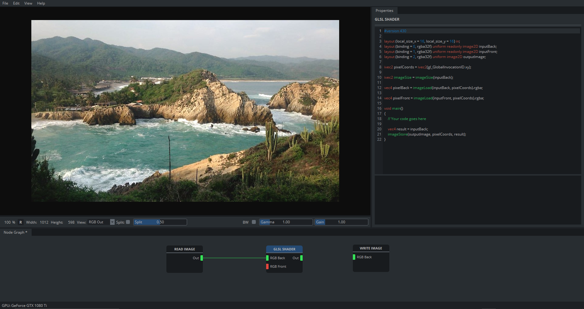
Your setup should look similar to this:
The default shader
The code editor contains the following:
#version 430

layout (local_size_x = 16, local_size_y = 16) in;
layout (binding = 0, rgba32f) uniform readonly image2D inputBack;
layout (binding = 1, rgba32f) uniform readonly image2D inputFront;
layout (binding = 2, rgba32f) uniform image2D outputImage;

ivec2 pixelCoords = ivec2(gl_GlobalInvocationID.xy);
ivec2 imgSize = imageSize(inputBack);
vec2 pixelCoordsNorm = vec2(float(pixelCoords.x) / imgSize.x, float(pixelCoords.y) / imgSize.y);

vec4 pixelBack = imageLoad(inputBack, pixelCoords).rgba;
vec4 pixelFront = imageLoad(inputFront, pixelCoords).rgba;

void main()
{
   // Your code goes here

   vec4 result = inputBack;
   imageStore(outputImage, pixelCoords, result);
}
Most of the things here you don’t have to worry about, let’s go through the important parts.
layout (local_size_x = 16, local_size_y = 16) in;
layout (binding = 0, rgba32f) uniform readonly image2D inputBack;
layout (binding = 1, rgba32f) uniform readonly image2D inputFront;
layout (binding = 2, rgba32f) uniform image2D outputImage;
In the beginning the inputs and outputs are declared. There are two images on the input side and one on the output. Since we only have the back input connected in the node graph, we are only going to use the inputBack image.
Following are a couple of convenience functions, to make life easier.
ivec2 pixelCoords = ivec2(gl_GlobalInvocationID.xy);
This gets the current pixel coordinates and stores them in the integer vector pixelCoords.
A GLSL shader gets executed for every pixel in the image. This variable tells us which pixel we are currently working on.
ivec2 imgSize = imageSize(inputBack);
This gets the image size and stores it in the variable imgSize for later use.
vec2 pixelCoordsNorm = vec2(float(pixelCoords.x) / imgSize.x, float(pixelCoords.y) / imgSize.y);
Calculates the normalized pixel coordinates and stores them in pixelCoordsNorm.
vec4 pixelBack = imageLoad(inputBack, pixelCoords).rgba;
Loads the RGBA values of the back image, at the current pixel coordinates, into pixelBack.
vec4 pixelFront = imageLoad(inputFront, pixelCoords).rgba;
Loads the RGBA values of the front image, at the current pixel coordinates, into pixelFront.
Since there is nothing connected to our front input, we ignore this value for the example.
Now, this is where it gets a little more interesting:
void main()
{
   // Your code goes here

   vec4 result = pixelBack;
   imageStore(outputImage, pixelCoords, result);
}
This is the main function and the entry point for our shader.
vec4 result = pixelBack;
imageStore(outputImage, pixelCoords, result);
Here you can see that the inputBack value is copied into result and then saved to the output image via imageStore.
That’s what this shader does, it copies the input to the output, without doing anything else.
Writing our own shader
Now, let’s see how we can do something with our image.
If you change the line
vec4 result = pixelBack;
to
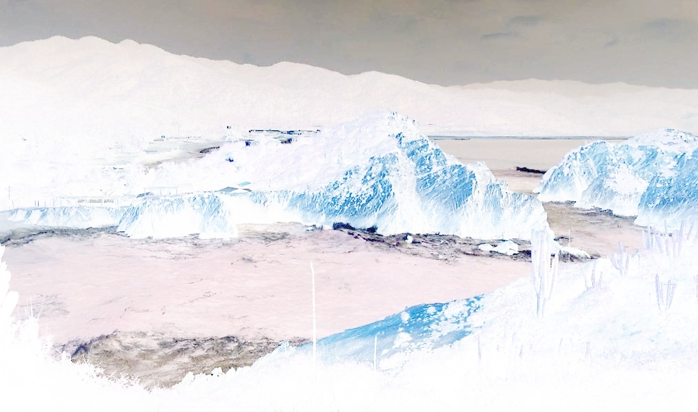
vec4 result = 1.0 - pixelBack;
you will see that this inverts our image.
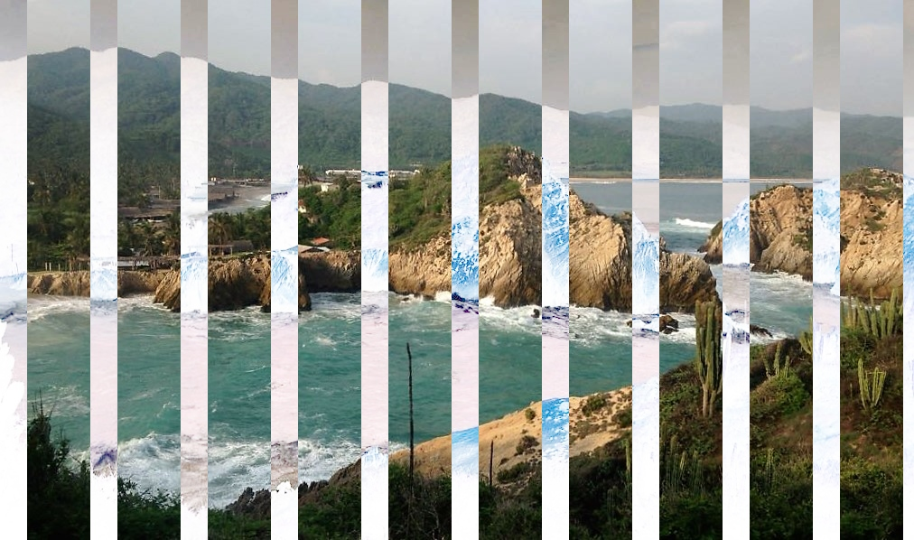
Let’s say we want some inverted vertical stripes, we could do something like this:
vec4 result = pixelBack;

if (pixelCoords.x % 100 < 30)
{
     result = 1.0 - pixelBack;
}
which gives us this:
Of course, this is a very simple example, but I hope it helps as an explanation on how to create your own effects in Cascade.
You could now render your image, using a write node. You can also save your node setup, including any shaders you created by going to File > Save Project.
If you need inspiration on shaders or you want to figure out how certain effects are implemented, I recommend checking out Shadertoy and ISF.